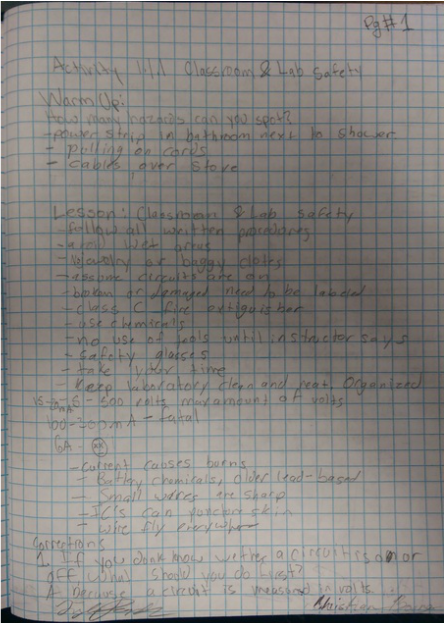
Activity 1.1.1 Classroom & lab safety
Description: basic classroom and lab safety
Activity 1.1.2 Scientific and engineering notation
Description: SCIENTIFIC AND ENGINEERING NOTATIONS ARE THE TWO MOST COMMON FORMS OF POWER-OF-TEN NOTATION. IN THE FIELD OF ELECTRONICS, ENGINEERING NOTATION IS THE PREFERRED NOTATION BECAUSE OF THE DIRECT MAPPING BETWEEN ITS POWERS AND THE INTERNATIONAL SYSTEM OF UNITS (THE INTERNATIONAL SYSTEM OF UNITS IS ABBREVIATED SI FROM THE FRENCH SYSTÈME INTERNATIONAL D'UNITÉS). THE SI SYSTEM IS THE MODERN FORM OF THE METRIC SYSTEM. IT IS THE WORLD'S MOST WIDELY USED SYSTEM OF UNITS FOR SCIENCE AND ENGINEERING.
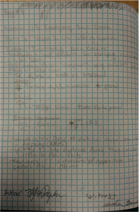
Activity 1.1.3 Investigating Basic Circuits
DESCRIPTION:
WHAT ARE VOLTAGE, CURRENT, AND RESISTANCE? HOW ARE THEY RELATED TO ONE ANOTHER?
- WHAT ARE SOME OF THE BASIC COMPONENTS THAT MAKE UP SIMPLE CIRCUITS AND WHAT DO THEY DO?
- WHAT ARE THE IMPORTANT CHARACTERISTICS OF A CIRCUIT AND HOW DO I MEASURE DIFFERENT PARTS OF A CIRCUIT?
- HOW DO I MEASURE VOLTAGE IN A CIRCUIT?
- HOW DOES THE ARRANGEMENT OF COMPONENTS AFFECT THE CHARACTERISTICS OF THE CIRCUIT?
- HOW DO I WORK SAFELY WITH CIRCUITS?
- HOW CAN I USE CALCULATIONS TO DESIGN CIRCUITS BEFORE I START CREATING ONE?
Activity 1.1.4 Component Identification: Analog
In the field of electronics, there are an endless number of different types of components. The ability to identify these components and to understand how they are labeled is an essential skill for anyone working in the field.
In this activity you will identify and determine the nominal values for a series of resistors and capacitors. We will concentrate on resistors and capacitors because they are part of virtually every electronics design ever made.
In this activity you will identify and determine the nominal values for a series of resistors and capacitors. We will concentrate on resistors and capacitors because they are part of virtually every electronics design ever made.
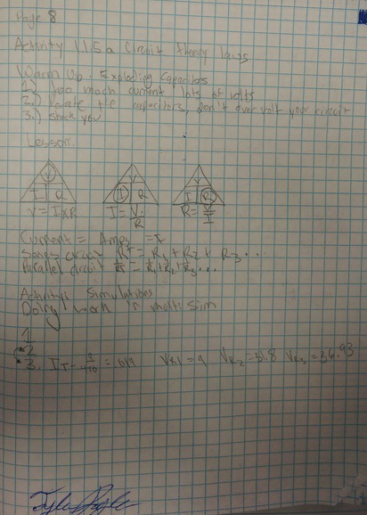
Activity 1.1.5a Circuit Theory: Hand Calculations
Have you ever used a calculator to add some numbers, looked at the answer, and realized that it was wrong? How did you know that the answer was incorrect? The calculator gave you an answer; why did you not trust it? You knew the answer was wrong because you understand the fundamentals of mathematics. Your instinct told you that the answer could not be correct.
The same is true for circuit analysis. Throughout this course you will be using Circuit Design Software (CDS) to test the circuits that you design. This software will always give an answer, whether it is right or wrong. The only way that you will be able to rely on these answers is if you have an understanding of the laws of circuit analysis. You must develop the same instinct for circuit behavior that you have for mathematics.
In this activity you will gain experience applying Ohm’s Law and Kirchhoff’s Voltage and Current Laws to solve simple series and parallel circuits.
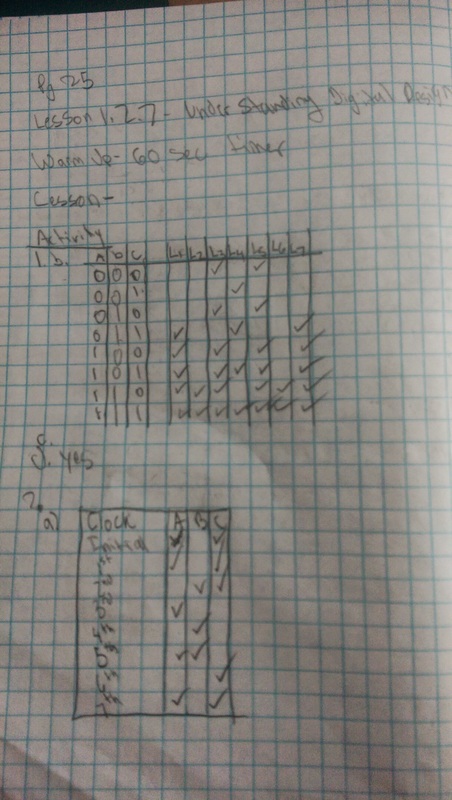
1.1.6 Digital component identification
In this activity you will investigate both combinational and sequential logic gates. You will be asked to simulate simple circuits using basic logic gates. You will then complete a truth table for each logic gate based on the outputs generated from your simulation. The name of many of the fundamental logic gates in digital electronics are based on the logic output from the gate. From analysis of a truth table, could you determine the name and understand function of the gate?
You will examine the basic building block of sequential logic: the flip-flop. The investigation will conclude with a look at the 555 IC and how it is used to trigger events in a circuit.
You will examine the basic building block of sequential logic: the flip-flop. The investigation will conclude with a look at the 555 IC and how it is used to trigger events in a circuit.
1.1.7 Introduction to Datasheets
Who fought in the Battle of Hastings in 1066? Who invented Silly Putty? Which of the Wright brothers flew first? All very important questions, but it would simply be impossible to keep all of the answers to such questions in your head. This is why we turn to the available resources like the Internet and textbooks to retrieve such information when necessary.
The same information overload is true when it comes to integrated circuits. What is the function of a MAN6760? How many pins does an LM555 Timer have? What is the maximum supply voltage for a 74LS08? All of this information and more is available in the manufacturer datasheet for each of these components.
In this activity you will learn how to obtain and extract information from the manufacturer datasheet for several components commonly used in digital electronics.
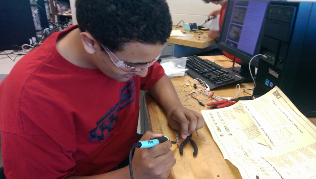
Project 1.1.8 Soldering Practice: Fun Light Project
Regardless of whether you have your driver’s license or will soon be getting it, two absolute certainties exist. One: you will want to drive your parents’ expensive car, and two: they will not let you. To a parent, the reasoning is obvious. When you are first learning to drive, you are most likely to make a mistake. Wouldn’t it be better to make these mistakes in the ten-year-old family minivan?
Like driving, good soldering requires practice. In this activity you will practice your soldering skills while constructing a simple Fun Light Project. This Fun Light Project has many of the same components as the Random Number Generator that you will construct in a future activity. Moreover, like the old minivan, if you happen to damage the Fun Light while honing your soldering skills, it’s not a big deal.
Like driving, good soldering requires practice. In this activity you will practice your soldering skills while constructing a simple Fun Light Project. This Fun Light Project has many of the same components as the Random Number Generator that you will construct in a future activity. Moreover, like the old minivan, if you happen to damage the Fun Light while honing your soldering skills, it’s not a big deal.

1.2.1 Introduction to Combinational Logic Design: Seat Belt Circuit
Combinational and sequential logic are the fundamental building blocks of digital electronics. Combinational logic, which is sometimes referred to as "combinatorial logic”, is characterized by its output being a function of the current input value.
A variety of different logic gates can be used to implement combinational logic circuits. Many of these gates will be studied in future units of this course. In this introductory unit, we will limit our designs to AND, OR, and INVERTER gates for the sake of simplicity.
In this activity you will use the Circuit Design Software (CDS) to build and test your first combinational logic circuits.
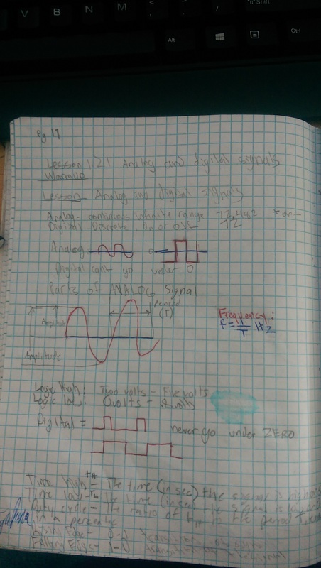
Activity 1.2.2 Analog and Digital Signals
Even though this is a course in digital electronics, it is important to understand that the world around us is analog. Virtually everything that can be designed with digital electronics is used to either control or monitor something in the world around us, and this world is analog. Thus, to be an effective designer of digital electronics, it is important for you to understand the characteristics of both analog and digital signals.
In this activity you will examine several analog and digital signals to determine their amplitude, period, and frequency. Additionally, you will gain experience using the oscilloscope within the Circuit Design Software (CDS).
In this activity you will examine several analog and digital signals to determine their amplitude, period, and frequency. Additionally, you will gain experience using the oscilloscope within the Circuit Design Software (CDS).
Activity 1.2.3 Binary Number Systems
Have you ever wondered why we use the base-ten, or decimal, number system? Of course, we have ten fingers. However, the decimal number system that works so well for us is completely incompatible with digital electronics. Digital electronics only understand two states, ON and OFF. This is why digital electronics use the base-two, or binary, number system. In order for you to be able to design digital electronics, you will need to be proficient at converting numbers between the decimal and binary number systems.
In this activity you will learn how to convert numbers between the decimal and binary number systems.
In this activity you will learn how to convert numbers between the decimal and binary number systems.
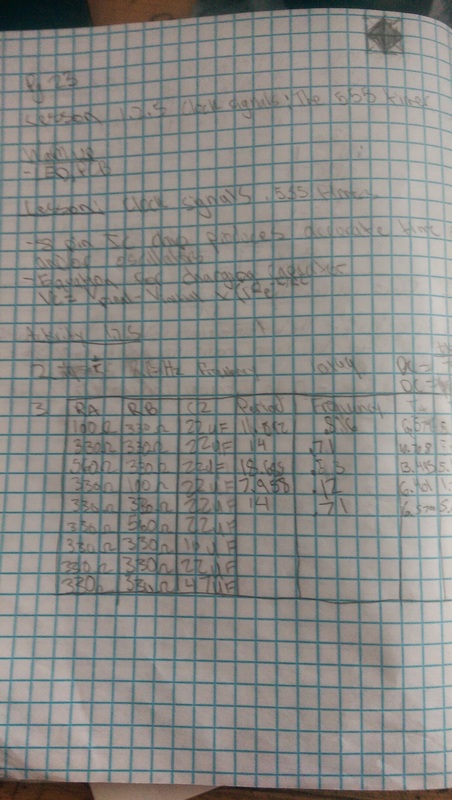
Activity 1.2.5 Clock signals: The 555 Timer
Almost all development tools used today in digital electronics have an internal clock that can be integrated into your circuit design. There are times however, when you may want to generate your own simple clock signal and not depend on the internal clock of your development board or equipment like a function generator or digital writer.
The 555 Timer oscillator is one of the most common circuits used in introductory electronics. It is a favorite among beginners because of its low cost and ease of design. These are precisely the same reasons the 555 Timer is used in the Random Number Generator design.
In this activity you will simulate and create a 555 Timer oscillator. You will observe the effect that varying the value of its resistor and capacitor values has on the oscillation frequency and duty cycle.
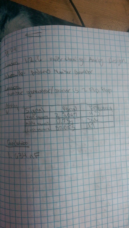
Project 1.2.6 Understanding Analog Design: Random Number Generator
The field of analog electronics is a unique discipline, distinct from the study of digital electronics. We have only scratched the surface of what you would learn if you continued your studies in this area. This project will be the last activity in our brief journey into the world of analog electronics.
In this activity you will use the Circuit Design Software (CDS) to build and test the complete analog section of the Random Number Generator design.
In this activity you will use the Circuit Design Software (CDS) to build and test the complete analog section of the Random Number Generator design.
Project 1.2.7 Understanding Digital Design: Random Number Generator
The Random Number Generator will be your first exposure to a fully developed circuit design that includes an analog section, a digital combinational logic section, and a digital sequential logic section. Combinational logic and sequential logic are the basic building blocks of all digital electronics and the topics of study for the majority of this course.
In this activity you will use the Circuit Design Software (CDS) to build and test the complete digital logic section of the Random Number Generator design
In this activity you will use the Circuit Design Software (CDS) to build and test the complete digital logic section of the Random Number Generator design